Shop parts by
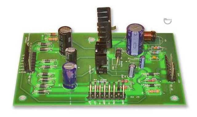
New No.GPS002 Gottlieb System 1 POWER SUPPLY BOARD. It's a superior replacement for Gottlieb System 1 pinball games when compared to the original board.
This plug and play unit has improvements in the areas of Heat Generation, Transformer Strain, Grounding, False Shutdown, Ease of Installation / Removal, Adjustment Elimination, Obsolete Part Elimination, and Aged Part Elimination.
Fits the following Gottlieb System 1 game titles:
ASTEROID ANNIE
BUCK ROGERS
CHARLIE'S ANGELS
CLEOPATRA
CLOSE ENCOUNTERS
COUNT DOWN
DRAGON
GENIE
INCREDIBLE HULK
JOKER POKER
PINBALL POOL
ROLLER DISCO
SINBAD
SOLAR RIDE
TORCH
TOTEM
TECHNICAL FEATURES OUTLINE and DISCUSSION:
Heat Generation
The original System 1 Power Supply was designed with linear voltage regulators for all DC outputs. These linear regulators include the high current +5V DC supply (which is internally current limited to approx 3.5A). The +5V supply alone can dissipate as much as 28 Watts of power in the form of heat. This heat generation is the reason the power supply PCB must be attached to a large metal heat sink / mounting plate. The full load efficiency of the original board can be no more than 36% (efficiency = Power Out / Power in = (5V*3.5A / 14V*3.5A)).
Transformer StrainThe inefficiency of the 5 volt supply under full load imposes a minimum of a 3.5A AC load on the +14V AC transformer. This high current causes premature aging of the transformer as well as the connectors in the path between it and the power supply. The
Select manufacturer to view game compatibility
To disassemble the original power supply:
1. Unsolder the large TO-3 transistor
2. Remove the 2 TO-220 bolts and isolators
3. Remove the two screws that hold the board onto the heatsink.
Once disassembled, the board will not work because the TO-3 transistor has been removed. This makes troubleshooting very difficult.
To re-assemble, reverse the above procedure and apply fresh heat sink compound to the large transistors.
The GPS002 PCB eliminates this entire procedure. It only takes 3 screws to remove the board from the mounting plate. Once the board is removed, you can troubleshoot the board with the power on because you have not removed a TO-3 transistor! Reassembly is just re-attaching the 3 screws.
Adjustment Elimination
The original System 1 board has two potentiometers that require adjustment for output voltage level and over voltage protection (see above). These adjustments require the use of a volt meter, screwdriver, and an extra hand. The GPS002 eliminates all board adjustments. It is truly a "Plug and Play" design. No adjustments, no potentiometers, no voltmeter are required.
Obsolete Part Elimination
Several of the parts on the original System 1 board are no longer available. If you search hard enough, you can find parts that are similar, but the reliability of old stock components may be questionable.
The GPS002 is made completely from new components that are currently available from many different suppliers.
Aged Part Elimination
Almost all existing System 1 boards are populated with components that are ~25 years old. The quality/reliability of semiconductor products designed for today's market are superior to those of the early 80's. Original electrolytic capacitors degrade with time and, though not yet defective, may not perform correctly.
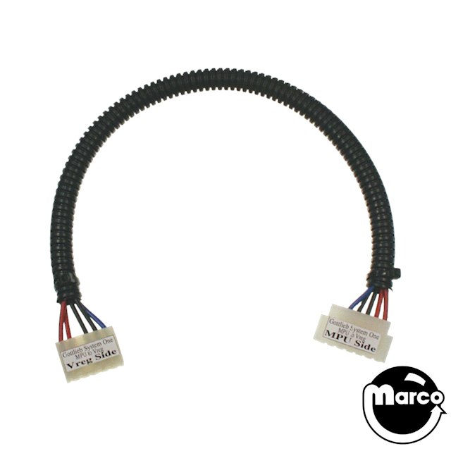
Cable for Gottlieb System 1 CPU to Power Supply
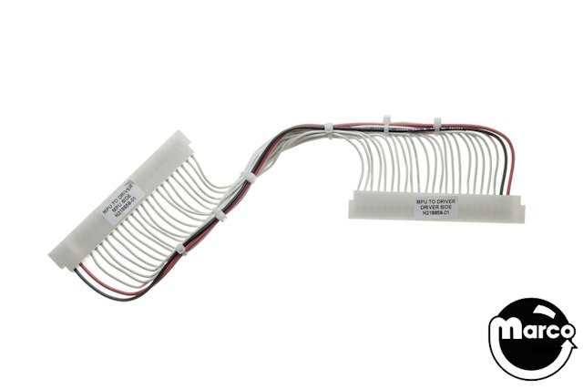
Cable connects the CPU board (A1-J5 connector) with the driver board.
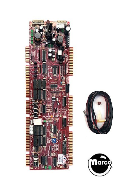
Gottlieb System 1 Replacement Board
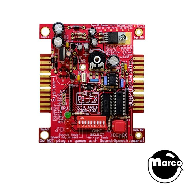
Sound Board For Gottlieb® System1, System80, 80A games
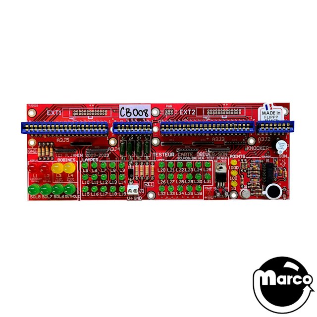
Test Fixture Gottlieb System 1 driver
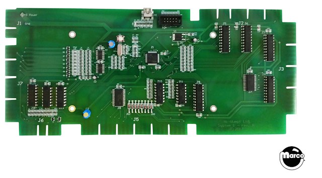
NEW! Ni-Wumpf MARK II CPU--REDESIGNED.