⚠ CALIFORNIA WARNING:
This product can expose you to chemicals, including lead and DEHP, which are known to the State of California to cause cancer and birth defects, or other reproductive harm. For more information, go to https://www.p65warnings.ca.gov.
2 board set of bench test equipment for Gottlieb® System 80, 80A, and 80B driver boards, designed by Pascal Janin.
Features:
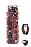
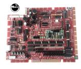
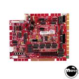
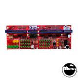
Large Board description
Large test board plugs directly into driver board A3J2 A3J3 A3J4 connectorsSecond small board tests the driver board A3J5 A3J6 connectorsPowered from the driver boardThrough-hole components for field serviceabilityLED indicator for each output (lamp, relay or coil)Each lamp output is labeled and grouped 4 x 4 (one group for each driver board 74175 chip)On-board load provides at least 300mA current draw per coil output protection against overloads (if one or more driver board transistors are bad)Additional external 5V input connector for additional powerEach L4...L51 output drives a 5mm LED indicator.SHOOT AGAIN lamps and GAME OVER and TILT relay outputs drive a 10mm LED.Coil outputs SOL1, SOL2, SOL5, SOL6, SOL9 on A3J4 drive a 10mm LED + a power load 12 ohms/5W resistor (that can be bypassed with a jumper).
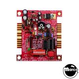
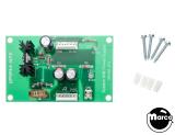
Small board description:
Board displays the signals coming from A3J5 and A3J6 : SOL3 SOL4 SOL7 SOL8 coilsCoin lockout coilS1 S2 S4 S8 sounds
The 5V general power supply is taken from A3J3 (and A3J5), with an overload protection (resettable polyswitch fuse). This protection is mandatory if the 5 coil outputs are used simultaneously (current > 500mA).
Screw terminal connectors can be used to power the board with a larger power supply if needed. Power input is selected via a 3-position jumper.
Please note that the polyswitch overcurrent protection only protects the 5V power supply coming thru A3J3 (A3J5).
CONNECTING and TESTING Instructions
The 3-position jumper selects the 5V source
position 1-2 (high): 5V from A3J3position 2-3 (low): 5V from the screw connector ( + = highest position pin, ground = lowest)
To test a driver board in an unknown condition, remove the 5 coil jumpers. This disconnects the load resistors.
The connectors are aligned with the driver ones. Switch OFF the pinball and insert the test board connectors into the driver board connectors. Then power ON.
At power up (immediately for System 80A games or after 5 seconds for System 80 games), the 2 TILT and GAME OVER LEDs briefly blink together, then the lamp LEDs will be driven by the CPU, or cycle if the attract mode has been activated.
No coil LED should be lit except if there is a fault on the driver board.