⚠ CALIFORNIA WARNING:
This product can expose you to chemicals, including lead and DEHP, which are known to the State of California to cause cancer and birth defects, or other reproductive harm. For more information, go to https://www.p65warnings.ca.gov.
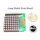
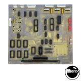
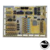
Lamp matrix simulator test fixture board for Williams pinball System 9-11 games.
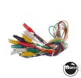
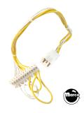
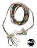
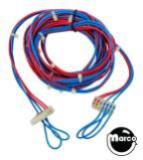
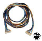
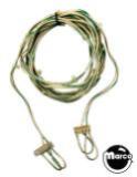
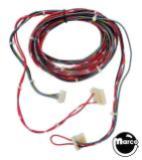
Simulates the playfield lamp matrix using a small 8x8 LED matrix display and allows you to quickly isolate a controlled lamp problem. Compatible with Williams System 9 through 11 games and Data East. Limited compatibility with Sega/Stern 'Whitestar' and SAM systems. Wire harness included.
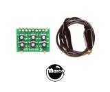
Operates either on the bench or with main boards mounted in the machine. This fully assembled circuit board includes pre-assembled wiring harness.
Select from the related items below for Williams System 3-7, or Williams /Bally WPC generation machines.
Bench Testing Lamp Power
Testing a game mounted driver board doesn't require any additional power to drive the LED matrix board. For bench testing, you'll need to supply power anywhere from 5 to 18 volts DC to the lamp matrix power input connector on your driver board.
System 3-7 the lamp matrix power input is at connector 2J4. System 9-11 the lamp matrix power input is at connector 1J4.
WPC89 and WPC95 boards have an integrated power supply, and we currently do not supply instructions for bench testing the lamp matrix outside of a machine.
Testing with the diagnostic board
The LED matrix board simulates the playfield lamp harness, meaning any time a lamp on the playfield turns on or off, an LED on the matrix block will replicate that. This occurs in any mode that would operate the switched lamps: attract mode, game play, or via the CPU board diagnostic routines.
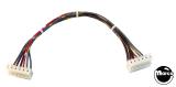
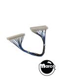
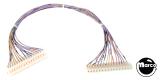
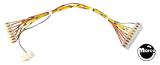
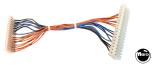
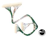
Simply attach the 16 pin connector onto the tester board, and the two 8 pin connectors onto your CPU/Driver board where indicated. These are the normal lamp matrix wiring connectors that connect your controlled playfield lights to the boards.
Generally, a CPU / Driver board problem will be related to a full lamp row or column. A single bad lamp is usually not a board problem, but is a harness problem. Circuit board issues are indicated by inoperative full rows and/or columns, or they will be locked on when they should be shut off. Once you identify a faulty lamp or column, then begin tracing back to the components on the board. These types of component level repairs should be attempted by experienced board repair technicians.
The tester board is oriented in the same direction as the lamp matrix diagrams in your game manual - Column 1 on the diagram will be the leftmost column on the tester board. Row 1 on the diagram is the top row of the tester. (Unless you wired it backwards).